Midi Mixer Controller on the ATmega32U4 (Arduino Pro Micro)
I always enjoy playing with microcontrollers and it's been a while since I last made an Arduino project.
After buying an Akai MPK Mini Play Mk3 for my son and being clearly a bit too excited about it I decided to buy an Akai MPK Mini Mk4 for myself since my Roland midi keyboard wouldn't fit on my desk.
I have been using Renoise to create music for a couple years now and I wanted to learn Reaper in order to teach my son how to use it with his newly acquired midi keyboard.
While looking at the Mk4 and its various buttons and encoders it made me curious about how I could build my own midi mixer controller with an Arduino.
This complete project would include a couple components, a bit of programming, a bit of soldering, learning a CAD software and creating a full-fledged 3D printed enclosure.
In other words, a great side project.
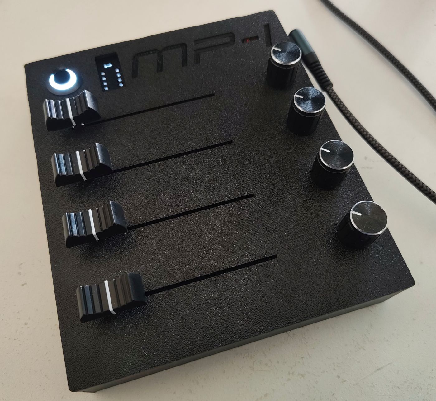
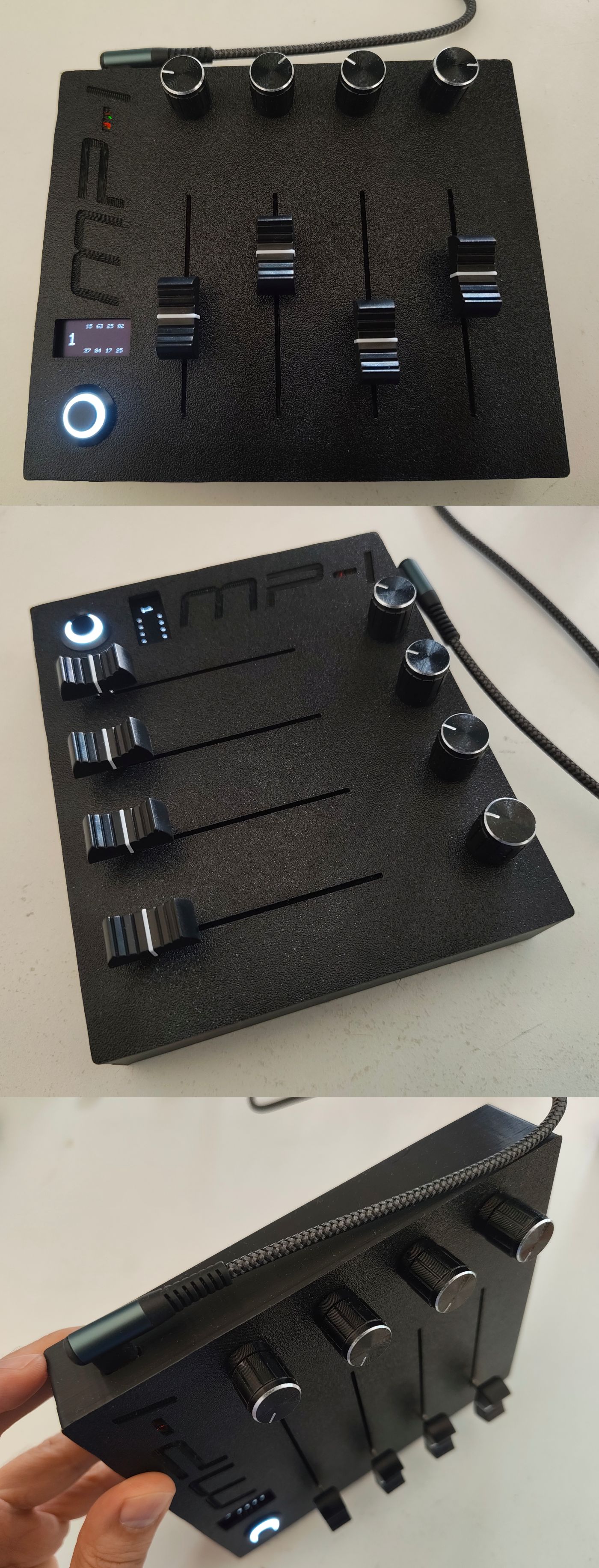
Behold ! The MP-I
This article is not an in-depth tutorial about creating a midi controller even though I suppose you could still follow up and recreate everything with the informations and assets provided.
The purpose of this page is that I mostly wanted to document how this went from an obsessive pet project idea to a real product.
When I have something in mind that really piques my curiosity I often have a hard time letting it go and with life and other obligations in the way it's often really hard to finish projects. This time though, I had to finish what I started as I also wanted to prove myself I could still complete something like that.
The MP-I (as in mrt-prodz-one.. I know.. how original..) project was born.
The plan
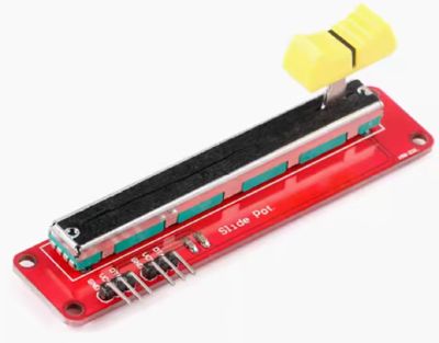
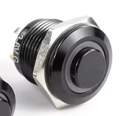
The plan was to make a small MIDI Mixer controller with a row of potentiometers along with another row of sliding potentiometers below them, a button to switch MIDI channels allowing me to go from 0 to 15 and finally a small OLED display to show current channel and potentiometers value.
Let's be honest, this project is quite simple and doesn't require any advanced knowledge, it's mostly about testing everything and taking your time especially during the soldering which will be the most critical part.
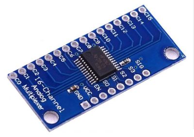
The easiest way to use an Arduino as a MIDI Class-Compliant device was to get an ATmega32U4 which can be found on an Arduino Micro, Pro Micro or Leonardo. It might sounds counter intuitive since I could technically wire everything directly on the Arduino itself, but using an Arduino Pro Micro for its small form factor along with a multiplexer made the wiring easier in my mind, so I went with a Pro Micro.
If I had a bigger 3D printer I could then easily double the number of potentiometers without changing a thing beside a couple lines of code. However my 3D printer as a bed of 180x180x180mm so I had to keep things compact enough.
For more information about MIDI Class-Compliant Arduino you can have a look at this nice article and video from Nerd Musician.
Here are the steps I followed:
- Find which components I need
- Figure out the most optimal wiring to make a compact device
- Buy components
- Make a prototype on a breadboard
- Program the Arduino
- Solder the main components on a stripboard
- Create an enclosure
- Challenge my patience
Components
I used to be a bit of a component hoarder but honestly, who started playing with microcontrollers without going on an impulse buying rampage ? After looking through what I already owned I realized I had a couple components already.
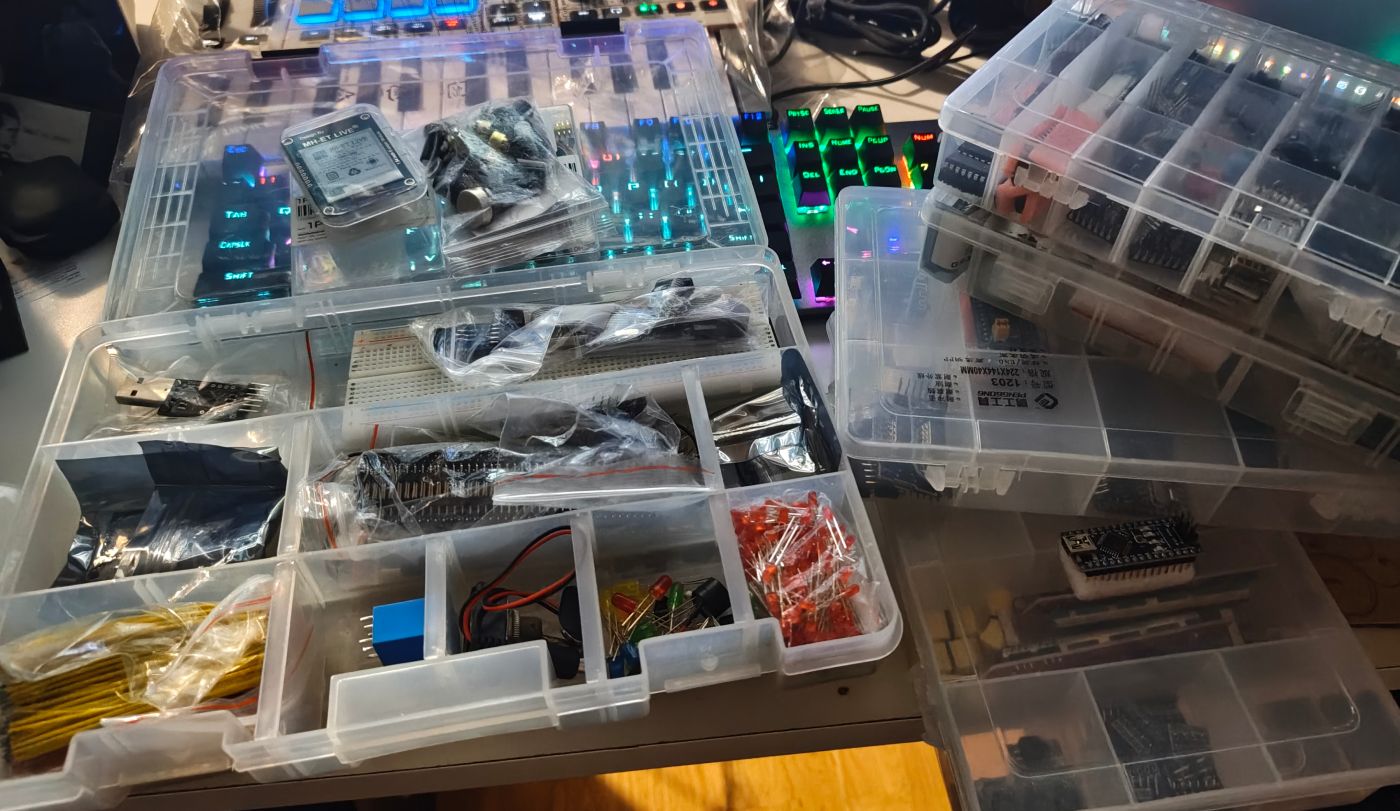
Ah! I knew it would come handy when I bought these.. years ago..
Further down below in this article you can find an approximate cost of all components and tools used for this project.
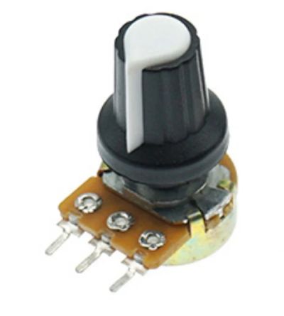
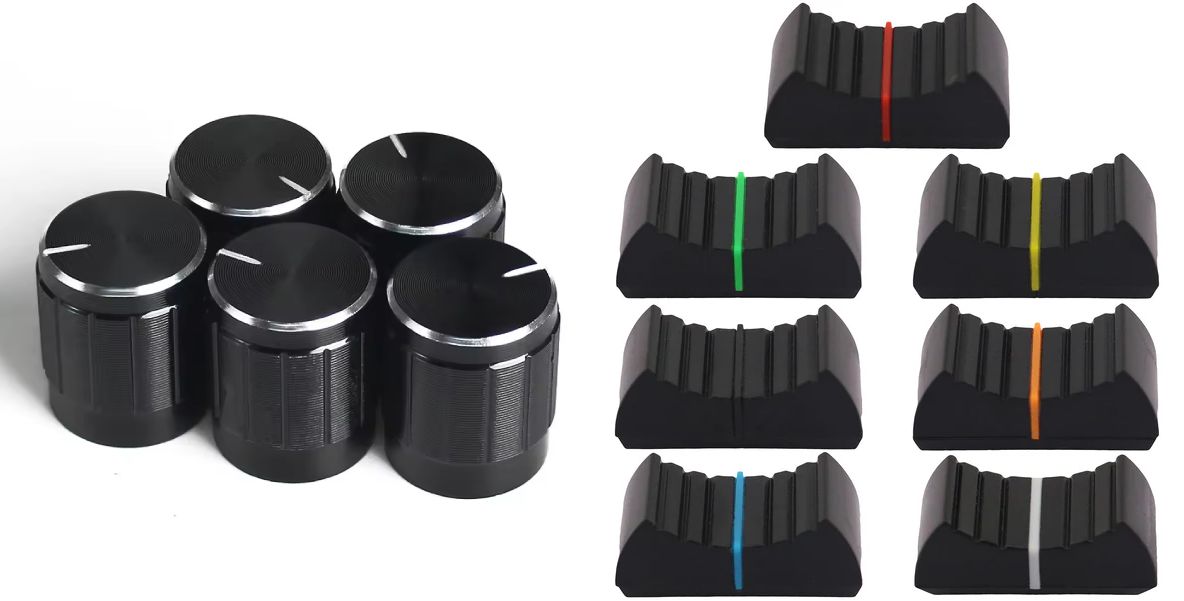
Here is the list of the main required components, one small advice would be that it's easier to build such project if you have twice the amount of components listed below. The reason being that you can make a prototype on a breadboard and use it as a reference while making your final project separately to avoid wiring error especially while soldering.

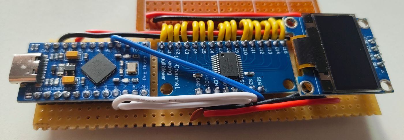
The prototype
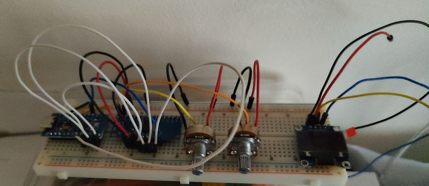
Once I had all components ready the next step was to create a small working prototype.
One thing to have in mind is that long loose wires on a breadboard might generate noise because of poor connectivity. Bumping your hand on a wire for example could make the reading of a potentiometer completely wrong.
The noise I had on the prototype was excessive compared to the final soldered product, however I did filter noise in both case with the software and a small capacitor to limit this issue as much as possible. Another reason could be that my breadboard and jumper wires are quite old by now.
The final purpose of the prototype was also to test all components independently. While you can see on the picture above that I only had two potentiometers connected to the multiplexer, I switched all my potentiometers in place to make sure they worked properly. I didn't want to risk soldering something that was not tested as it would make troubleshooting really hard: is it the component ? my wiring ? my soldering ? my code ? etc.. testing all components first is an important step and can be done quickly.
The wiring

The wiring is as follow:
- Multiplexer to the Arduino Pro Micro
| CD74HC4067 | Arduino Pro Micro |
|---|---|
| S0 | 9 |
| S1 | 8 |
| S2 | 7 |
| S3 | 6 |
| SIG | A0 |
| EN | GND |
- Channels used on the multiplexer by the potentiometers
| CD74HC4067 | Potentiometer number (output pin) |
|---|---|
| C0 | 1 |
| C1 | 2 |
| C2 | 3 |
| C3 | 4 |
| C12 | 5 |
| C13 | 6 |
| C14 | 7 |
| C15 | 8 |
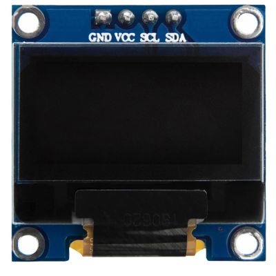
- 0.96 inch IIC Oled 128x64 to the Arduino Pro Micro
| IIC Oled | Arduino Pro Micro |
|---|---|
| SCK | 3 |
| SDA | 2 |
- Self reset button with integrated led to the Arduino Pro Micro
| Button | Arduino Pro Micro |
|---|---|
| COM | 4 |
And finally a 0.1µF capacitor between VCC and GND for the CD74HC4067 multiplexer to stabilize and reduce noise.
The program
There is sadly nothing exciting about the code running on the Arduino Pro Micro:
- reading potentiometers value through the multiplexer
- sending MIDI events when changing values
- updating the OLED screen when a value changes
- changing the MIDI channel when we press the button and using a debounce routine
Reading values through the multiplexer is well documented, here is a nice tutorial from Adam Meyer about Muxing Around With The CD74HC4067 + Arduino.
To send MIDI events I used the MIDIUSB Library for Arduino.
Since the program wasn't taking much space I decided to make a small splash screen when the device is starting with the logo of the website along with the model name. It somehow made it look like a more polished final product:
To make the logo I used Photopea to resize it to 32x32px and reduced the color to 2 (black and white).
After that I could either use Gimp and export to C array or this great online tool File to C style array converter and simply copy the result in a header file.
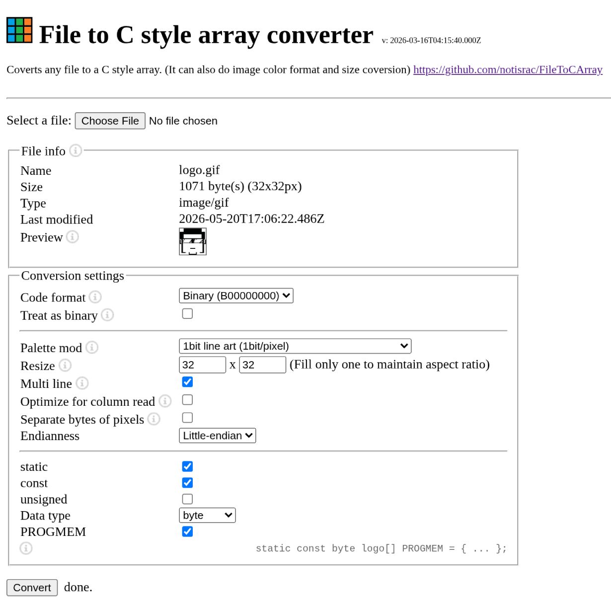
The resulting header should have an array of binary values, since we only need a black or white value per pixel we save a lot of space that way by storing 8 pixels per byte.
You should get something similar to this:
static const uint8_t PROGMEM LOGO_BMP[] =
{
	0b00000111,0b11111111,0b11111111,0b11000000,
	0b00001111,0b11111111,0b11111111,0b11100000,
	0b00001111,0b11111111,0b11111111,0b11100000,
  ...
You can find the project repository further below.
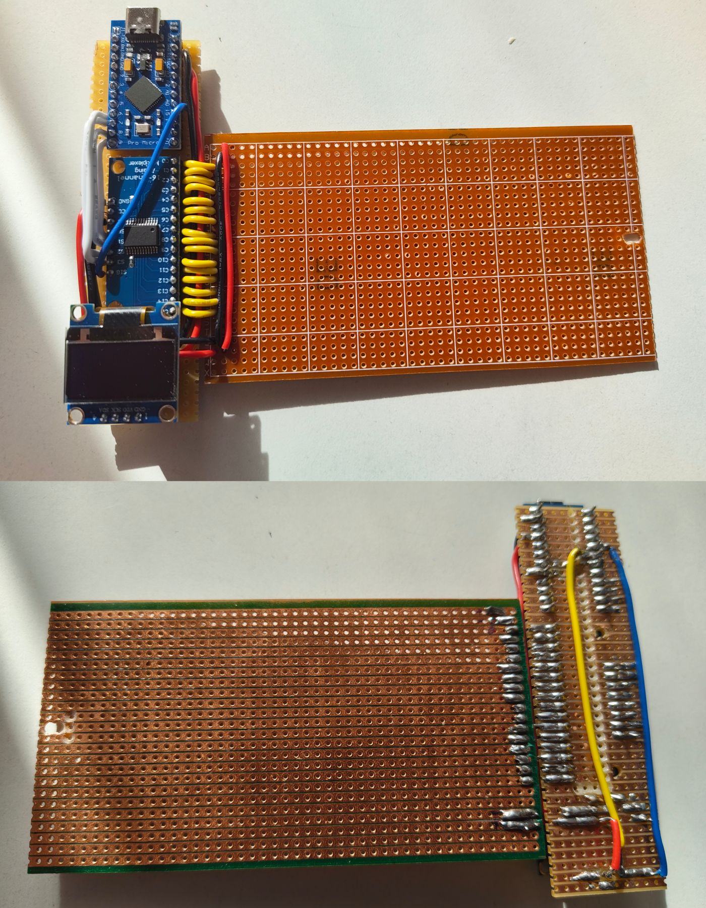
The stripboard
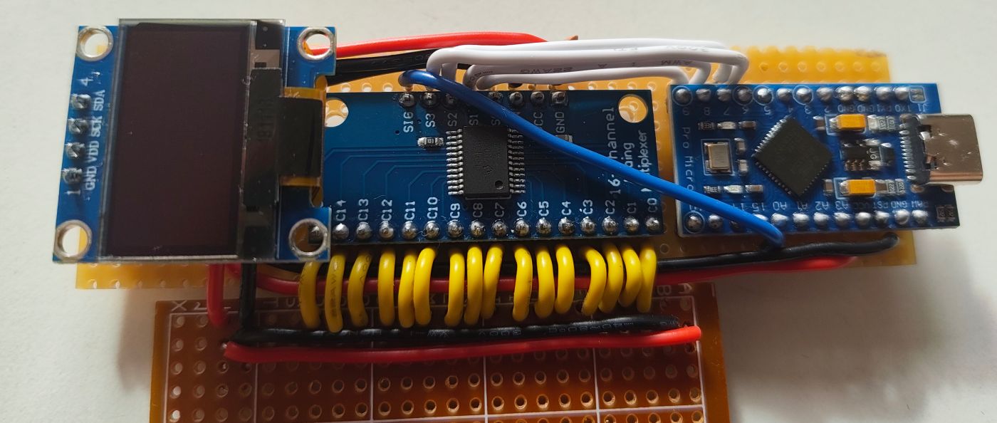
Before even starting with the soldering iron, I had to prepare the stripboard first and cut connectivity to make sure the components I planned to solder on won't mess with each other.
Cutting the connection of a stripboard is really easy, placing a small 3 millimeters drill bit where we want to cut the connection and gently turning the drill a couple times without applying too much force is enough to do such task.
To make sure we drilled enough into the stripboard we then take our multimeter and make sure the connectivity between both stripes is cut. In the following picture you can see that I also made a couple cuts with a cutter but it's really unnecessary.
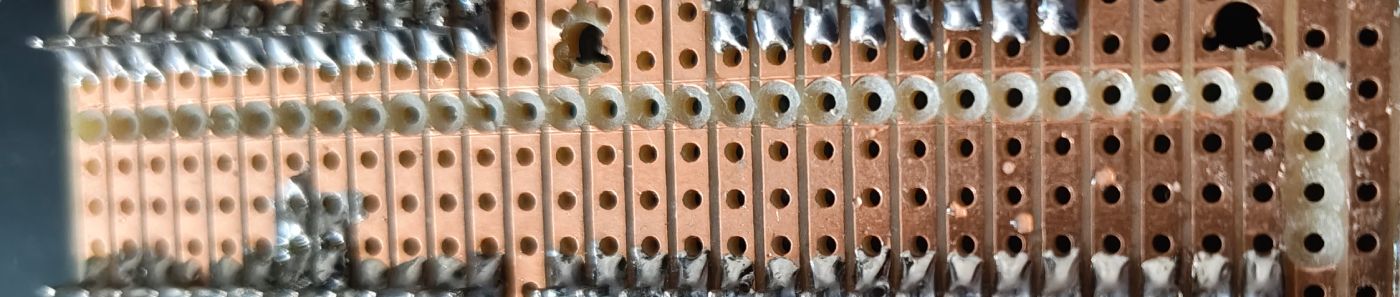
Since I didn't have a big enough stripboard I had to combine two of them, cutting a stripboard is quite easy when using a ruler and a cutter. You guide the cutter with a ruler through the holes where you want to cut and you slice the board a couple times deep enough on both sides. Then you only need to snap the stripboard and you should get a nice clean cut.
I can't stress enough the fact that buying a kit of 22AWG solid wires was simply the best decision I made. I never worked with solid wires before but it's so easy to shape them and avoid making a huge spaghetti mess that I'm not sure I'll ever work with anything else.
Here is how the stripboard ended up looking:
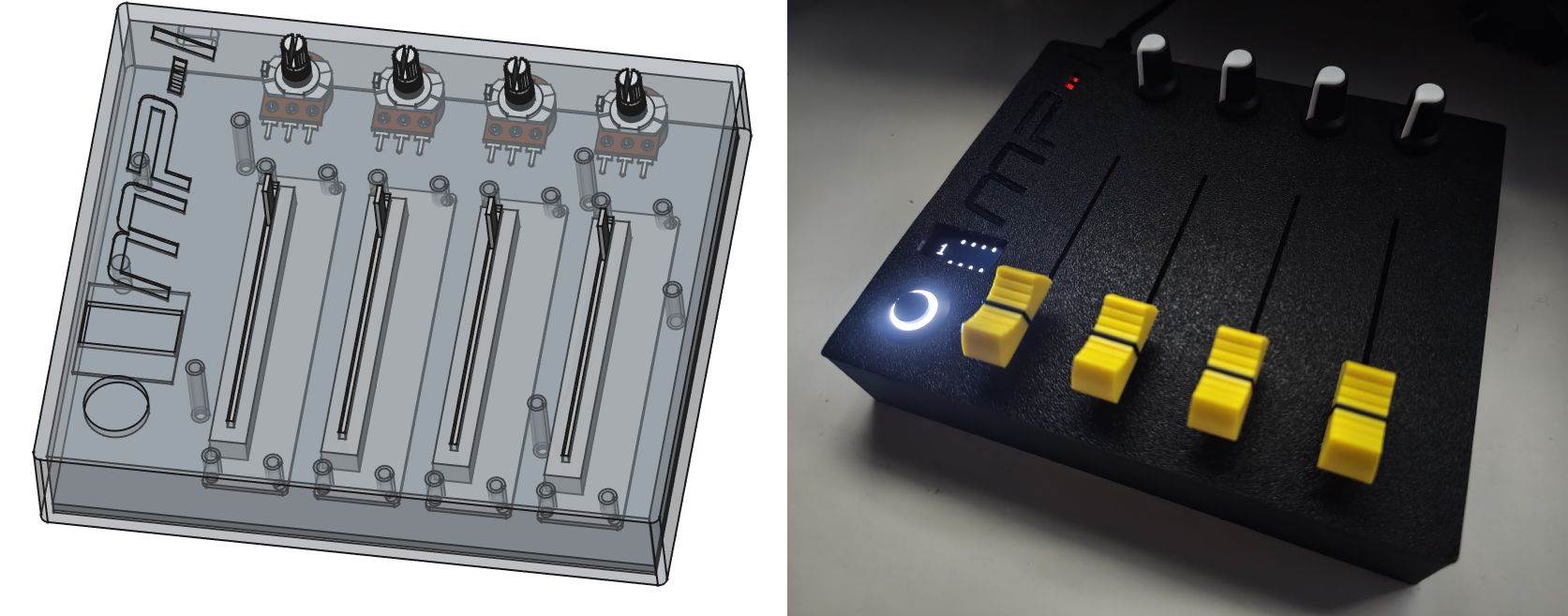
The 3D printed enclosure
Beside taking a lot of measurements, finding 3D models of your components can help a lot as long as they have the proper dimensions. I found both type of potentiometers on GrabCAD Community Library and beside the sliding potentiometer which was a couple millimeters off everything else was perfect and pretty useful.
I decided to make the 3D model with FreeCAD which is completely.. well.. free as the name implies. The learning curve might be a bit steep, but once you understand how things work you can quickly make simple models such as the one created for this project. It is a great software.
To avoid wasting PLA filament and time, I sliced the model and printed only the part that required testing as I progressed with the 3D model to make sure the measurements were correct.
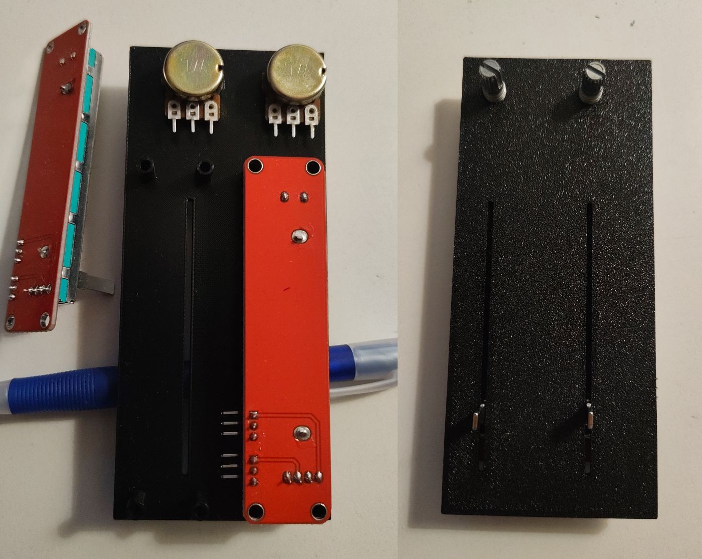
And this is the final 3D model I ended up making, you can find both FreeCAD and STL files in the project repository. I made two small holes in the dash between MP and I to have the led of the Arduino Pro Micro shine through when the device is on.
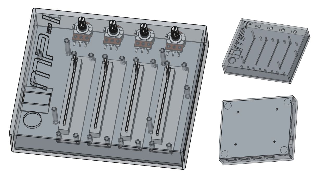
Printing the body on a Bambu Lab A1 Mini took:
- 2 hours and 42 minutes for the body
- 1 hour and 6 minutes for the back cover
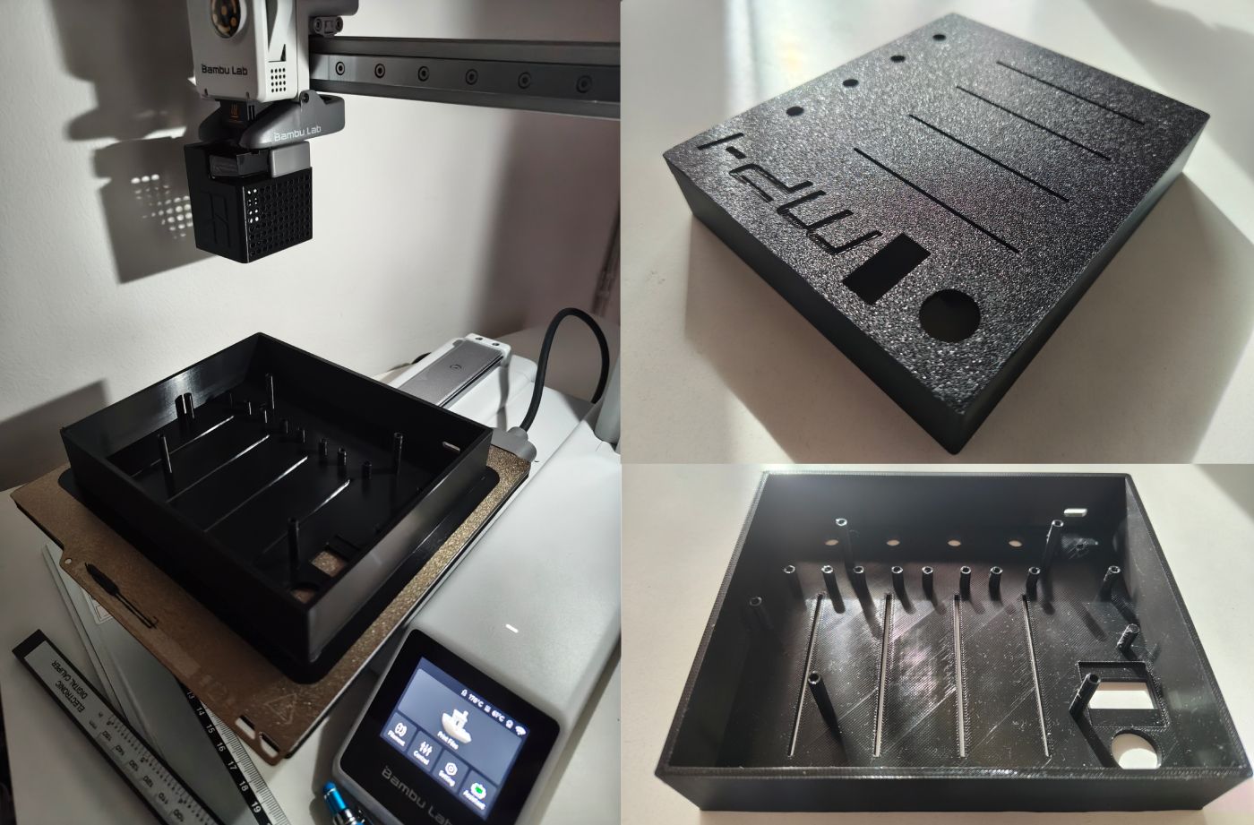
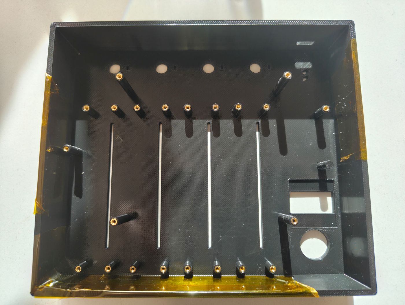
Installing the brass threaded inserts
This is the first time I used inserts for a project and it was quite easy to work with. The idea is to use the heat of the soldering iron to warm the insert enough that it will melt the plastic and slide into it. As soon as the area is cooling the insert will be firmly stuck into the enclosure.
If you are careful enough this is not a required step but to avoid melting nearby plastic by accident I used high temperature heat resistant tape.
With my soldering iron set to 170 degres, I gently pushed each insert into the plastic enclosure, no strength required at all as they were almost sliding by themselves with the heat.
Combining everything together
To avoid any mistake and eventually having to desolder anything I soldered long wires on purpose to give me enough room for their routing.
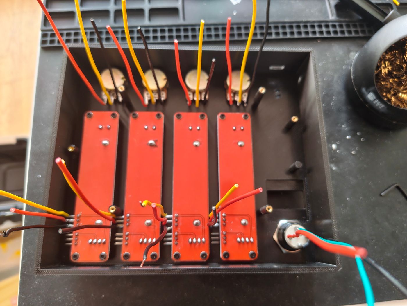
To make sure I would not have any issue I 3D printed some tiny washers to avoid any direct contact between the M3 screws and the stripboard. I also made a small spacer between the stripboard and the multiplexer to avoid breaking anything with the screw going through.
After soldering each component I would turn on the device and test it to make sure it is working properly, my goal was to avoid soldering everything and having to figure out what went wrong if something was not working as intended. Fortunately, everything went smoothly and I didn't encounter any issue.
And once I was sure that all components were working I finally put the back cover on. In each corner of the back cover I set small indented areas if I ever wanted to stick anti-slip pads.
I like the fact that the end result is an enclosure that is not too bulky, it actually has the same height as my MIDI keyboard.
The mistakes
It OLED where you said ?
While I did try to plan everything ahead, I still had a couple of small mishaps which were fortunately easy to circumvent.
One of those mistake was that I misplaced by one row the OLED display, I have absolutely no idea how it happened because I was supposed to solder the header on the very last row of the stripboard but here I was, soldering like a mad man and only once done, realized that it was too high and obstructing the second screw (out of 3) I planned to use to fix the board to the enclosure.
This was not a big deal since I placed the back cover screws close enough to the board on purpose to keep the board still, but this is the reason why the 3D printed enclosure has one of its feet without any insert in it.
Soldering 16 channels only to use 8 ?
Now if you take a good look at the wiring and stripboard pictures, you might have wondered why I soldered 16 channels while only using half of them. Well, when you look at where the rows of potentiometers are placed in the enclosure it actually makes sens to use the first 4 and last 4 channels because of where I had to solder their pins.
Since I'm using solid 22AWG wires, soldering all these channels actually helped both stripboards stay in place as if it was one solid piece. It was also a good solution to make a hole where the unused channels are to fix the stripboard to the enclosure.
After writing all these fake excuses I can just honestly say that I was on some sort of automatic mode and soldered everything without even realizing half of these were not needed..
You can't disassemble it anymore ?
I'm still unsure about that one but maybe I should have used JST connectors instead of soldering everything directly on the board. On one hand, it keeps things compact enough but on the other I'm not able to remove the stripboard from the enclosure without desoldering all potentiometers and button because the top sliding potentiometers screws are behind the stripboard.
Final touch
You can further customize the look of the MIDI Mixer Controller by using lesser toy looking caps, just make sur about their dimensions and compatibility with the potentiometers.
Furthermore
Another thing would be to stick, 3D print or paint visual markings to quickly show the actual intensity of the potentiometers.
One last final touch would be to sand and polish the 3D printed enclosure to give a smoother look.
Approximative cost of this project (prices in Euros)
Here is an approximative cost breakdown regarding components used for this project.
Required components
| Component | Quantity | Unit price | Total Price |
|---|---|---|---|
| Arduino Pro Micro | 1 | 3.99 | 3.99 |
| 10K Ohm Sliding Potentiometer with cap | 4 | 1.80 | 7.20 |
| 1NO 16mm Self Reset 3-6V Button with integrated led | 1 | 2.42 | 2.42 |
| 0.96 inch IIC Oled 128x64 | 1 | 1.49 | 1.49 |
| Total | 15.10 € |
Required items which can be used for other projects because of bulk purchase
| Component | Unit price | Required | Estimated Cost |
|---|---|---|---|
| 5pcs 10K Ohm Potentiometer with bolt and cap | 1.59 | 4 | 1.27 |
| 10 pcs CD74HC4067 Multiplexer | 4.30 | 1 | 0.43 |
| 100 pcs 0.1µF 104PF Ceramic Capacitor | 1.63 | 1 | 0.01 |
| 660 pcs M2 Screws Set M2 | 7.49 | 22 | 0.24 |
| 330 pcs Brass Threaded Insert Nut Kit M2 / M3 / M4 | 9.29 | 22 | 0.61 |
| 5 pcs 65 x 145mm PCB Board 2.54mm Grid Size (stripboard) | 0.99 | 1 | 0.19 |
| 25 pcs 50 x 100mm PCB Board 2.54mm Grid Size (stripboard) | 17.69 | 1 | 0.70 |
| 22AWG Solid Wire Kit (6 colors, 5m each) | 19.99 | ~100cm | 0.66 |
| 1kg Black 1.75mm PLA | 11.32 | ~135gr | 1.52 |
| Solder Wire 100g | 11.99 | ~20gr | 2.39 |
| Total | 7.92 € |
Beside these components, various tools were being used for this project and the 3d printer was the most expensive of all.
Required tools
| Tool | Unit Price |
|---|---|
| Multimeter | 18.80 |
| Soldering Iron Kit | 13.89 |
| Rotary Tool Set (Mini Drill) | 36.17 |
| Cutter | 3.81 |
| Wire Stripper | 9.99 |
| Long Nose Pliers | 7.99 |
| 3mm Drill Bit | 2.91 |
| Bambu Lab A1 Mini 3D Printer | 189.00 |
Repository
You can find the source and FreeCAD file on github: github.com/mrt-prodz/mp-i